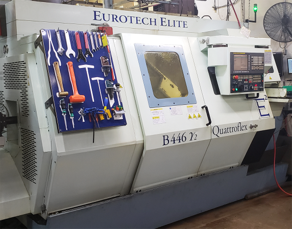
2011 Eurotech Elite Trofeo B446 SY2
5-Axis or More CNC Lathes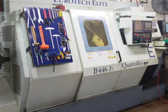
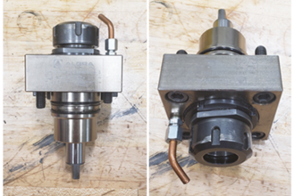
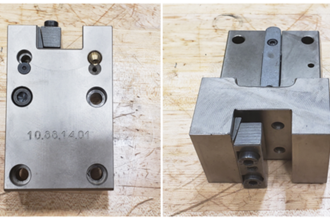
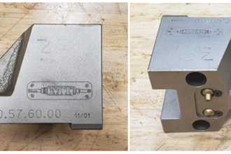
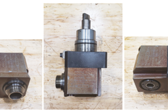
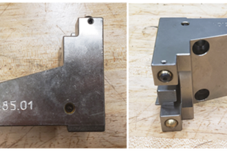
Tool Holder Package
Fanuc Control
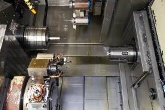
C Axis on Both Spindles
Clearshift on the Sub Spindle
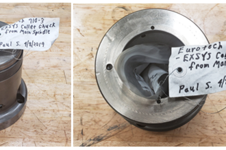
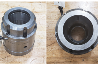
Collet Chucks for the Main and the Sub Spindle
| # Axis | 6 |
| Swing | 20" |
| Chuck Size | 8" |
| Bar Capacity | 2" |
| Power | 20 hp |
| Max RPM | 5,000 RPM |
| Turning Dia | 9.6" |
| Tailstock | No |
MACHINING CAPACITY
Maximum bar capacity................... 2.00”
Maximum turning diameter............................................. 8”
Maximum stroke Y-axis stroke (both) ....................... 3.54”
CHUCK WORK
Chuck diameter - (main spindle)............................. 8”
- (sub-spindle) ............................... 8”
Type..................................................................... hydraulic
Maximum speed ............................................... 5,000 RPM
MAIN SPINDLE
Draw-tube capacity......................... 1.77” (2.00” Optional)
Spindle through bore capacity.................................... 2.17”
Spindle speed range (infinitely variable)................... 5,000
Variable speed steps........................................ Direct drive
Spindle motor (Fanuc 22S)....................................... 20 HP
Motor type .............................................................. S series
Spindle nose ............................................................... A2-5
SUB-SPINDLE
Drawtube capacity.......................... 1.81” (2.05” Optional)
Spindle through bore capacity.................................... 2.17”
Spindle speed range (infinitely variable)................... 5,000
Spindle drive motor (variable speed) max. rating ... 15 HP
Spindle nose ............................................................... A2-5
Slide movement - (B-axis) ................. NC control
Slide stroke - (B-axis) ........................ 26.37”
UPPER TURRET
Number of tool stations (main spindle).......................... 12
Turret indexing time....................................... 0.10 sec/pos.
Turret indexing type ...... Fanuc servo-driven bi-directional
Slide stroke:
Z-axis...................................................................... 24.8”
X-axis ....................................................................... 6.7”
LOWER TURRET
Number of tool stations (main spindle) ..................... 12
Turret indexing time .................................. 0.10 sec/pos.
Turret indexing type . Fanuc servo-driven bi-directional
Slide stroke:
Z-axis............................................................... 21.26”
X-axis................................................................... 6.7”
REVOLVING TOOL ATTACHMENT
UPPER/LOWER TURRET
Number of upper turret positions ...................... 12 max
Number of lower turret positions....................... 12 max
Drive motor – maximum rating
(upper and lower turrets) ................................. AC HP 5
Speed range (infinitely variable) ........................... 4000
Revolving tool axis............................. X, C, Z & Y
Y Axis Strokes (both) ..................... +1.97”/ -1.57”
GENERAL INFORMATION
Voltage required ........................... 400 volt AC, 3-phase
Air Supply............................................ 80 psi @ 4 CFM
Amperage Draw............................................. 120 Amp.
MACHINE DIMENSIONS
Width. ................................................................... 85.0”
Height ................................................................... 87.0”
Length with chip conveyor................................. 179.0”
Machine weight with chip conveyor............. 15,874 lbs.
NOTE: Horsepower given are the 30 min. ratings.
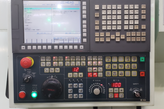
EUROTECH FANUC 31i CONTROL
STANDARD FEATURES
FANUC:
- Spindle and axes motors, drives, and
transducers by FANUC
- A.C. spindle and axes motors (Brushless)
- Central unit incl. Pentium processor (32
bits)
- Least input increment : 0.001 mm
- Least command increment: 0.001 mm
- Millimeter data input
- 10.4 LCD graphic display (liquid crystal
display) - low radiation emission
- Electronic hand wheel
- RS 232 interface with connector
- Memory card reader placed near the screen
incl. protection door
PROGRAMMING FUNCTIONS:
- Diameter and millimeter programming
without decimal point
- Constant cutting speed (G96)
- Tool radius compensation (G40-G41-G42)
- Graphic display
- Canned cycle for turning (roughening -
outside/inside finishing - grooves - profile
repetition )
- Canned cycle for drilling (chip breaking and
removal)
- Direct programming using drawing
dimensions and code A (Angle), R (Radius)
and
- C (Chamfer).
- Canned cycle for threading (G76-G78)
- Up to 3 M functions on same Block
- Input of local coordinates G52
- Machine coordinates selection G53 for tool
change position
- Automatic choice of offset value by simply
calling relevant turret position (T6 = T0606)
- Type B Macro instructions, fixed and
changeable variables after turning machine
power off
- Call of sub-programs (M98)
- Call of macro-instructions (G65 - G66)
- Display of actual spindle speed output (even
if program includes G96)
- Table of tool geometry
- Table of offset values for tool wear
compensation with safety (max. input value:
0.999)
- Limit of axes rapid speed (operator panel)
- Display of operator messages in English
- Display of axes and spindle motor power
absorption
EUROTECH OPERATOR PANEL:
- Keyboard featuring an anti-splash
membrane and LED inside
- Machine operational mode change-over
switch
- Spindle rotation speed change-over switch
(override)
- Graduated handle control for axes feed rate
and rapid
- Emergency mushroom switch (red)
- LED indicator for % spindle rpm
- LED indicator for tool position
- 2 position key selector to by-pass safety
mechanisms
- 3 position key selector which acts on use of
operational mode change-over switch
- Cycle start push-button (cycle)
- Hold push-button for spindle axes drive
- Switch to by-pass coolant, also in manual
mode
- Toggle switch for block-by-block operation
- Toggle switch for block skipping
- Toggle switch for optional stop M01
- Switch for inside lightening
- Change-over switch for main or sub-spindle
- Buttons to move “X”, “Z”, “B”, “Y”, “C”
axes
- Dry-run button
- Button for spindle rotation clockwise, in
reverse mode and spindle stop
- Button for chip conveyor (run - stop)
- Button for machine additional lubrication
- Buttons to set turret position and
clockwise/reverse rotation
- Button for spindle collet clamp/unclamp
- Button to operate parts catcher forward
- Button for sub-spindle collet clamp/unclamp
- Button to hydraulically operate tailstock
forward/backward
• SBS Tool Load Monitoring